what is PCI?


PCI (Peripheral Component Interconnect) is a computer bus used for attaching peripheral devices to a computer motherboard. It is the most popular local I/O bus used in today. PCI provides a shared data path between the CPU and peripheral controllers in every computer models, from laptops to mainframes. Developed by the Intel Corporation, PCI first appeared in computers in 1993 and co-existed with the ISA bus for several years. It soon displaced the ISA and VESA local bus and became the standard expansion bus used in PCs. Today, most computers have only PCI slots and one AGP slot for a display adapter.

PCI supports both 32-bit and 64-bit data paths and can run at clock speeds of 33MHz or 66MHz. When implemented at 32 bits and 33 MHz, PCI yields a throughput rate of 133 MBps. PCI also has the ability to support bus mastering. The PCI specification covers the physical size of the bus, including wire spacing, bus timing, electrical characteristics, and protocols. The specification can be purchased from the PCISIG also known as the PCI Special Interest Group.
PCI Configuration

PCI devices are plug and play devices, meaning they load automatically when you connect them. Generally, the system firmware inspects each device's PCI Configuration Space and distributes resources accordingly. A device can request up to six areas of I/O port space or memory space. Each device can also have an additional ROM which can include executable x86 or PA-RISC code, an EFI driver, or an Open Firmware.

While configuring PCI, interrupts are usually allocated to the device by firmware rather than using jumpers on the card. System software tries to assign specific interrupts to each device to boost their performance. Most PCI devices require special hardware to support sharing an interrupt port because it needs a method to inform if an interrupt is for itself or for a specific device sharing the IO port.
History of PCI

Intel Corporation started the work on Peripheral Component Interconnect or PCI in 1990. On June 22 1992, PCI 1.0 was introduced in the computer world. PCI 1.0 was just a component-level specification. PCI 2.0, released in the next year, was the first to establish standards for the connector and motherboard slot. PCI was implemented in servers and eventually it replaced the MCA and EISA and became the server expansion bus of choice.

However, PCI took some time to supercede VESA Local Bus, commonly known as VLB; it also took some time to become the basic I/O bus standard in second-generation Pentium computers. By 1996 VESA Local Bus become extinct and PCI was adopted by almost all manufactures, even in 486 computers. But EISA survived a bit longer, until 2000. PCI was also adopted by Apple Computer for their professional Power Macintosh computers in mid 1995. The consumer Performa product line also adopted PCI in mid-1996, replacing LC PDS.

PCI added several new features and performance improvements in its latest versions. This includes a 66 MHz 3.3 V standard and 133 MHz PCI-X. Another improvement is the adaptation of PCI signaling to other form factors. The serial PCI Express standard, introduced in 2004, is the latest release in the computer market and has been well received.
PCI Express

PCI Express, formerly 3GIO/Arapaho, is a brand new interface developed using PCI programming concepts. PCI Express features a serial physical-layer protocol and various connectors. PCI Express is expected to replace the PCI and PCI derived AGP buses in the future.

Fire wire details


Firewire, also known as IEEE 1394 and i.Link, is a high speed serial bus developed by Texas Instruments and Apple computers in the mid 1990s. Firewire is compatible with more than 63 electronic and digital devices, which makes it a great choice for many people. Technically speaking, Firewire is a PC serial bus interface standard that offers isochronous data services and high-speed communications between digital devices. Basically, Firewire facilitates faster data transfer rates and usability across multiple devices.

Firewire is similar to Universal Serial Bus (USB), but it has a higher data transfer capacity - up to 800 Mbps, compared to the USB's 480 Mbps. This makes it ideal for peripherals that require high-speed data transfer, such as digital camcorders, DVD players and digital audio equipment.

Originally developed as a serial replacement for the SCSI Bus, Firewire was proposed to the IEEE by Apple computers in 1995. Sony has an implementation of the same standard known as i.Link, which is a four pin design as opposed to the original six pin model, which was made exclusively for Sony i.Link products.

Firewire 400, the first model to be introduced, had data transfer speeds of 100, 200, and 400 Mbps. Firewire 800 was introduced in 2003 and has a transfer rate of 800 Mbps, it also comes with a six pin connector that makes it compatible with the earlier Firewire 400. Thanks to the low start up costs and more adaptable cabling system, Firewire has successfully replaced SCSI in many applications. Firewire is widely used in situations where there is simply a need for data transfer at the highest speeds possible. Most personal computers come in with a built in Firewire port, as do many MP3 players.

Firewire gets a lot of positive recognition because it provides high speed, better power distribution, and does not require a computer host for its functioning. Firewire also gets a lot of attention because it outdoes SCSI capabilities in the way of higher sustained data transfer rates, which audio and video editors require. Most would also agree that the Firewire is advantageous because it can be daisy chained to extend it to many times a single cable length.

Compared to SCSI or USB, it can be seen that Firewire easily outperforms the other technologies because it is more robust, efficient, and has some great features. Some of the great things are that Firewire can be used to connect 63 peripherals in a cyclic network structure where SCSI follows a linear structure. Firewire also facilitates peer-to-peer device communications without using PC memory. Firewire also permits multiple hosts per bus, without the aid of an additional chip set like a USB cable. Firewire also supports plug and play and acts as a useful power cord for moderately power consuming devices.
Firewire Features

FireWire can connect up to 63 devices together, and allows peer-to-peer connectivity (i.e., between a camera and printer). It also uses isochronous real time data services which allows for real-time data transfer between a peripheral (i.e., a camcorder) and a host computer or device, with guaranteed bandwidth and no error correction.

This allows users to edit and create custom video projects with fast hard drives, a digital camcorder and a computer. Given the right software, a computer can download material from the camera automatically and with perfect digital clarity. Since the content is digital from start to finish, there is no loss of quality as you work on successive generations using the same material.
How FireWire Works

When you turn on a computer, it automatically queries all peripherals attached to it, and assigns each one an address in a process called enumeration. FireWire makes use of 64-bit fixed addressing, based on the IEEE 1212 standard. Each packet of information sent by a peripheral over FireWire has three parts:

* A 10-bit bus ID, to determine which FireWire bus generated the data,
* A 6-bit physical ID to identify the device which sent the data, and
* A 48-bit storage area capable of addressing 256 terabytes of information for each node.

The bus and physical ID comprise the 16-bit node ID, which allows for 64,000 nodes on a system. Data can be sent through up to 16 hops (device to device). Hops take place when a series of devices are connected.

For example, a camcorder is connected to an external hard drive attached to Computer A. The latter is then linked to Computer B, which is in turn coupled to Computer C. All devices can then access and make use of the camcorder; Computer C, however, requires four hops to access the camera. If all of the devices in this setup are equipped with FireWire 800, the camcorder can be up to 400 meters from Computer C (given 100 meters of cable between each device).

FireWire devices can be powered or un-powered; two power conductors built into the cable can supply power (8 to 30 volts, 1.5 amps maximum) from the computer to an un-powered device. Two twisted pair sets carry the data in a FireWire 400 cable using a 6-pin configuration. Some smaller FireWire-enabled devices use 4-pin connectors to save space, omitting the two pins used to supply power.

upgrading motherboards


Motherboards hold all the pieces that make up your computer. It supplies all the wiring and connections needed to make your computer run. However, you may feel that need to upgrade or replace your motherboard.

Before anything can be done, you need to be absolutely sure that you have to upgrade your motherboard. As a stand-alone part, motherboards are probably the part that would least likely need an upgrade. Some reasons for having to upgrade would be:

* Not enough space for an adequate amount of RAM
* No slot for an adequate graphics card
* Damage to the actual motherboard

You then need to decide whether you want to keep the current parts of your computer, or buy completely new ones along with your motherboard.
Keeping the Same Parts

If you want to keep the same parts in you computer after purchasing a new motherboard, you need to start by looking at the parts you already have. In this way, you need to look for a motherboard that is compatible with your existing computer parts. This is essential because you do not want to buy a motherboard that is not compatible with any of the parts you already have.

You may not know what parts your computer consists of. To find this out:

* Right click on 'My Computer'
* Go to Properties
* Go under Hardware
* Click Device Manager

You can now see all the parts that your computer has. Remember to write these down for future reference.

After doing this, you can start looking for a motherboard. Sites such as Newegg are a great way to compare and contrast different models.

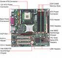
When looking for a motherboard, make sure that it has the following:

* Enough RAM slots
* A PCI slot that is compatible with your graphics card
* A CPU Socket that is compatible with your CPU
* Enough USB drives to comfortably fit everything you may want to plug in
* Optional: Onboard sound to save some money and have a spare PCI slot

Once you have chosen a motherboard, be sure to double check that all existing parts fit.
Buying New Parts

If you want to completely upgrade your PC and buy new components along with you motherboard, you are effectively building a new computer.

All the parts that you choose must be based from your motherboard. Each part must be compatible with the motherboard you choose in order for your computer to run.

When buying a brand new motherboard, look for:

* Enough RAM slots
* A PCI Express slot for a good graphics card
* A widely accepted CPU slot to increase your CPU model options
* Optional: Onboard sound

Once you have purchased your motherboard, you are ready to install it.
Taking out the Motherboard

You will need just a screwdriver for the entire process

1. First, disconnect all the wires behind your computer
2. Start by taking out the largest wire that connects the power supply to the motherboard
3. Move onto the smaller wires that are used for processes such as LED, Power Switch and Reset Button
4. Take the larger ones out next: the wires running from the read/write drive and hard drive.
5. Open the case - you may need to use a screwdriver for this
6. 'Ground' yourself by touching the large metal bar across the computer towards the top. Static electricity can completely destroy parts. Doing this gets rid of the static electricity in your body
7. Start by taking off all the wires that are connected into the motherboard. You can move these wires to the side.
8. The graphics card is located towards the bottom of the motherboard. There will most likely be a switch or latch where the graphics card extends to the back of the computer. Lift or switch this latch.
9. Very gently, begin by pulling up the end of the graphics card is closest to the back of the computer. This side should lift up.
10. There is a hook on the other end of the graphics card. Be aware of this when fully detaching the card. Lay the card to the side when you are done.
11. You now have to take off the heat sink and fan located on the CPU.
12. Detach the wire from the heat sink and fan from the motherboard.
13. Depending on what model of CPU you have, you need to take off the heat sink and fan first. There should be a latch that you lift that will release both the heat sink and fan.
14. You now need to take out the actual motherboard.
15. There will be screw all around your motherboard. Unscrew these and you should be able to lift it up out of the computer relatively easy.
16. Once you have the motherboard out, you need to take off the RAM and actual CPU.
17. Lift the metal latch located above the CPU socket.
18. Gently lift the CPU up and off the motherboard. You may need to move it from side to side a little to loosen it.
19. On either side of the RAM will be some handles. Push these down and the RAM card should pop right out. Be careful to not use too much force.

Remember:

* No water or food anywhere near where you are working
* Never use force if something is not going right

Re-Attaching the New Motherboard

Once you have successfully taken out your old motherboard, you can now proceed to install the new one. The steps taken here are basically the same as detaching the motherboard, but in the opposite way.

1. First, put the CPU onto the motherboard and close the metal latch.
2. Open the handles on the RAM slots and push the RAM into it. There are corresponding holes on the RAM cards so make sure these are aligned.
3. You should here a click with the RAM is attached properly.
4. Take the motherboard and place it in the computer.
5. Depending on the two types of motherboard you have, you may need to realign the 'legs' that the motherboard is screwed onto. In this case, take out the legs and screw them back in the corresponding shape to the larger holes on the motherboard.
6. After doing this, screw in the motherboard.
7. Plug the power supply into the motherboard.
8. As before, you now need to replace the heat sink and fan on the motherboard. Place them onto the CPU and latch it in.
9. Remember to plug the wire leading out of the fan into the motherboard for power.
10. You now need to install your graphics card.
11. Sliding in the end of the graphics card that has the hook first, slowly lower the other end until it fits nicely onto the motherboard. You may need to lift or switch a handle to secure it in place.
12. You now have to reattach all the wires you took out.
13. Start with the larger ones. Since you should not have removed the read/write drive and hard drive when taking out your motherboard, they should still be in place. Plug these into the respective slots.
14. Now plug the rest of the wires in.

Remember:

In doubt, always refer to the motherboard manual.
Testing the new Motherboard

After installing your new motherboard, you are ready to test it out. Reconnect all the wires you had into their respective slots on the back panel.

Turn the computer on. If you hear a beep, that is the sound of the motherboard detecting the hard drive. This is perfectly normal.

Changing your motherboard should not result in any major changes to the software on your computer. Make sure that everything still runs smoothly.

No "Starting Windows 98" Message at Startup

when you start Windows 98 you do not see a "Starting Windows 98" message, and you cannot tell when to press the CTRL key to display the Windows 98 Startup menu.

The prompt has been removed to allow for a faster start of Windows 98


To display the Startup menu, press and hold down the CTRL key when your computer starts.

NOTE: If you press and hold down the CTRL key when your computer starts, you may receive a keyboard error message. If this occurs, you may safely ignore the keyboard error message.

If you want the Windows 98 Startup menu to appear each time you start your computer, follow these steps:

1. Click Start, click Run, type the following command in the Open box, and then press ENTER:

msconfig
2. Click Advanced on the General tab, and then click the Enable Startup Menu check box to select it.
3. Click OK, click OK, and then click Yes.

APPLIES TO

* Microsoft Windows 98 Standard Edition